
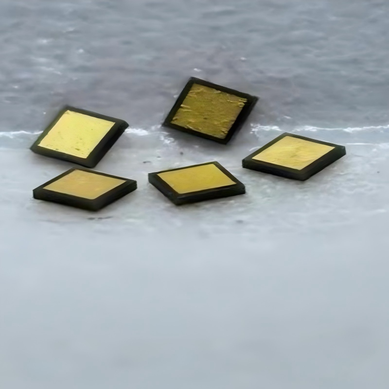
Descripción del Producto
Se utiliza principalmente en circuitos integrados de microondas (MIC) para el bloqueo de CC, la derivación de RF, la derivación de la fuente y la adaptación de impedancias.
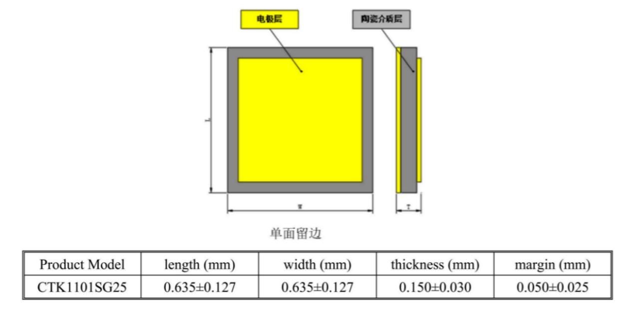
La especificación general es GJB2442-2021, la especificación detallada es ZZR-Q/TJKJ20007-2019, CTK1101SG es un condensador cerámico fijo de chip monocapa de uso general con un nivel de tasa de fallos, y el número de estándar es JLCH61020094, que presenta un excelente rendimiento de microondas con una frecuencia aplicable de 100 kHz a 100 GHz, y electrodos de oro superficiales adecuados para la unión con hilo de oro y cinta de oro.
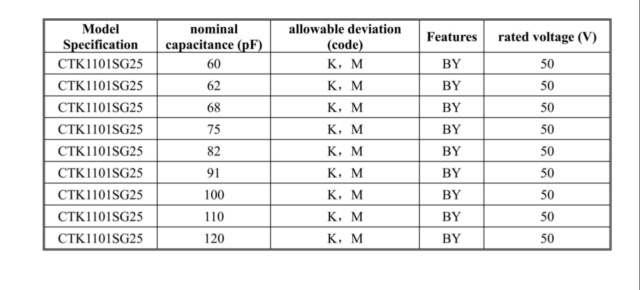
Capacidad :
60 pF ~ 120 pFVoltaje :
50VTolerancia :
K: ±10%; M: ±20%Tamaño :
CTK1101SG25Dieléctrico :
BYCalificación :
National Military StandardTiempo de espera :
8~12 weeks
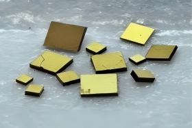
Descripción del Producto Los condensadores cerámicos de chip para microondas de uso general se utilizan principalmente en circuitos integrados de microondas (MIC) para el bloqueo de CC, la derivación de RF, la derivación de la fuente y la adaptación de impedancias. Se caracterizan por su pequeño tamaño, alta capacitancia, excelente rendimiento en microondas y un rango de frecuencia aplicable desde CC hasta 100 GHz. Los electrodos de oro superficiales son adecuados para la unión con hilo y cinta de oro.
LEER MÁS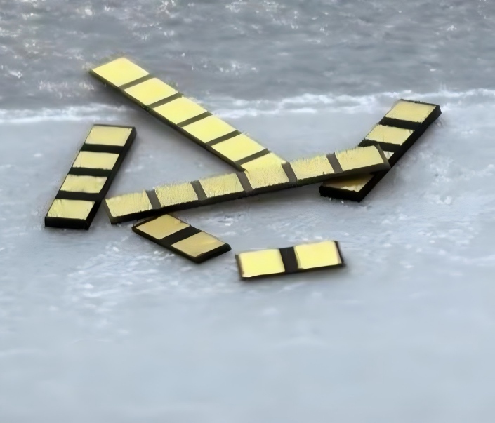
Descripción del Producto Se utiliza principalmente en circuitos integrados de microondas (MIC) para el bloqueo de CC, la derivación de RF, la derivación de la fuente y la adaptación de impedancias. De fácil montaje, puede reducir la longitud de los cables y mejorar el rendimiento en el encapsulado de circuitos integrados, al tiempo que reduce la complejidad y el coste del ensamblaje.
LEER MÁS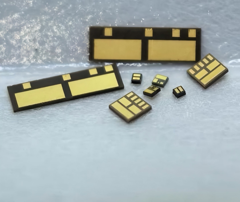
Descripción del Producto Se utiliza principalmente para la adaptación de impedancias, circuitos resonantes paralelos, sintonización por resonancia dieléctrica y acoplamiento. Fácil de montar y adecuado para el diseño y ajuste de circuitos.
LEER MÁS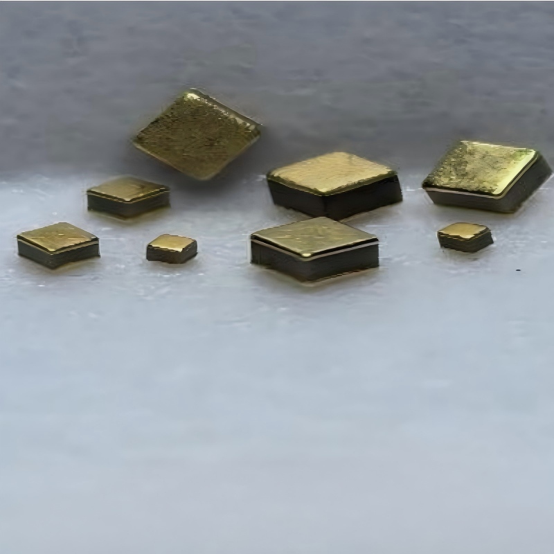
Descripción del Producto Se utiliza principalmente en filtrado de alto voltaje, derivación, etc. Tamaño reducido y alta capacitancia (1 nF~10 μF), con un buen coeficiente de temperatura de capacitancia y un alto voltaje de funcionamiento de hasta 100 V.
LEER MÁS
Descripción del Producto Se utiliza principalmente en circuitos integrados de microondas (MIC) para el bloqueo de CC, la derivación de RF, la derivación de la fuente y la adaptación de impedancias. La especificación general es GJB2442-2021, la especificación detallada es ZZR-Q/TJKJ20007-2019, CTK1101SG es un condensador cerámico fijo de chip monocapa de uso general con un nivel de tasa de fallos, y el número de estándar es JLCH61020094, que presenta un excelente rendimiento de microondas con una frecuencia aplicable de 100 kHz a 100 GHz, y electrodos de oro superficiales adecuados para la unión con hilo de oro y cinta de oro.
LEER MÁS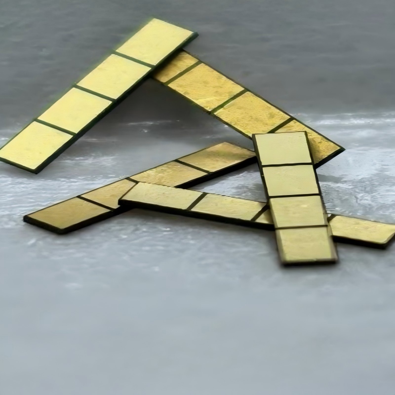
Descripción del Producto La especificación general es GJB2442-2021, la especificación detallada es ZZR-Q/TJKJ20008-2019, condensador fijo cerámico de chip monocapa tipo matriz CTK1101SA con nivel de tasa de fallos, y el número de estándar es JLCH61020095. Se caracteriza por su fácil montaje, menor longitud de los cables, alto rendimiento en el ensamblaje de circuitos integrados, baja complejidad de ensamblaje y bajo costo.
LEER MÁS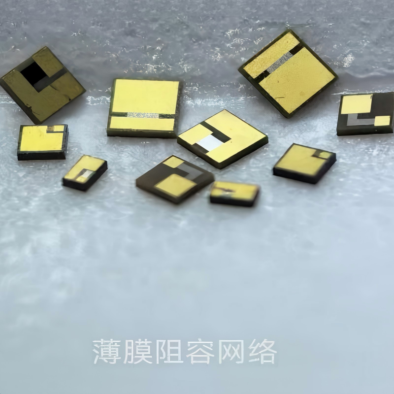
I. Applications Mainly used in microwave integrated circuits (MICs) to reduce circuit area and component cost. II. Features ◼ Resistors and capacitors are integrated together, reducing the number of components; ◼ Gold wire bonding is possible; ◼ Tantalum nitride film.
LEER MÁS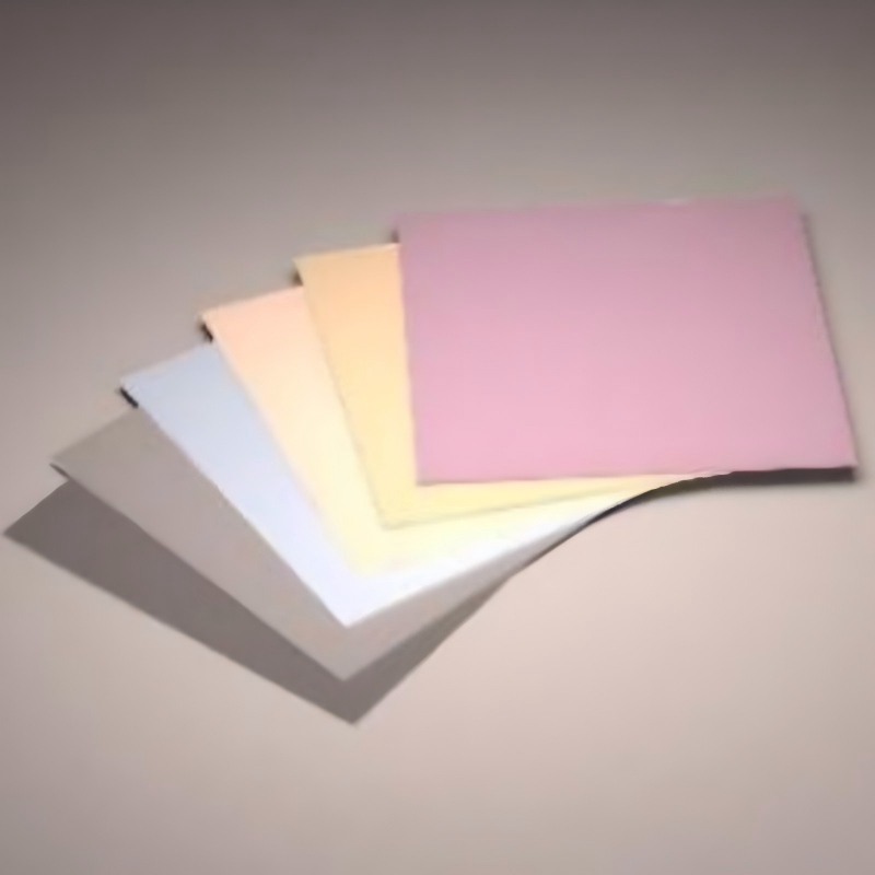
I. Aplicaciones Se utiliza principalmente para la fabricación de circuitos de película delgada, condensadores cerámicos de chips para microondas, etc. II. Características ◼ alto factor de calidad, alta constante dieléctrica 14~150; ◼ Coeficiente de temperatura de frecuencia de resonancia cercano a cero, que proporciona excelente estabilidad térmica; ◼ Sustratos planos, disponibles hasta 2 pulgadas; ◼ Se puede utilizar para fabricar condensadores de chips cerámicos de microondas, delgados.circuitos de película, antenas dieléctricas de microondas y otros componentes.
LEER MÁS


 Soporta red IPv6